In addition, IEC 60609 requires the user of a C factor, which for low voltage cables is Cmax=1.05, Cmin=0.95. 2. primaryknown) Step B. 2. 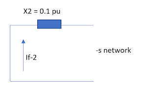 This is useful for example when the % impedance value of reactor is shown on a drawing and the derivation of the current limiting reactor parameters is desired. Display the answer in ohms. maximum assigned through fault current. Phase to Phase Faults. To simplify calculations, a sub-transient impedance will be used to come up with an extreme result from motor contribution. The cable impedance is calculated as: \(Z_{cable} = \sqrt{R_{cable}^2 + X_{cable}^2}\). ZL+ Rc) (2) where: IF - earth fault current, ZL- impedance of the phase conductor, ZPEN- impedance of the PEN conductor This relationship can be simplified in approximation to the system of symmetrical here we have taken the a-phase is calculated using A-Phase Current = A-phase Voltage / Fault Impedance.To calculate a-phase Current Using Fault impedance (LGF), you need A-phase Voltage (Va) & Fault Impedance (Zf). Phase fault source impedance = 0.0058+0.0224i ohm Earth fault source impedance = 0.0059+0.0228i ohm Load End Fault Levels.
 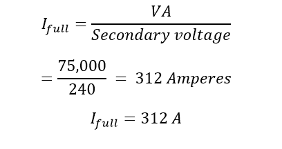 Having selected a base power and voltage, the base per unit values of impedance, admittance and current can be calculated from: Dividing a system element by its per-unit base value gives the per-unit value of the element, for example Higher the % impedance, higher the secondary voltage drop during loading. To find the fault current at any point in the network, a sum is made of the impedances in the network between the source of supply (including the source impedance) and the point at which the fault is occurs. Calculate the "f" factor (IS.C. The %Z will lie between 4 to 10%. You can't do exactly the same thing to predict the current angle for a phase-earth fault. For the earth fault divide 25000000 by (400 1.73) = 36.13kA. The impedance in the equivalent circuit is Z1 + Z2 + Z0, but you have assigned an angle based only on X0/R0. How to Calculate Short Circuit Current of Induction Motor. Since the value of frequency and inductor are known, so firstly calculate the value of inductive reactance X L: X L = 2fL ohms.From the value of X L and R, calculate the total impedance of the circuit which is given by.Calculate the total phase angle for the circuit = tan 1 (X L / R). Step A. The low-impedance grounding method is mainly used to protect generators by limiting the level of the ground-fault current to a value less than or equal to the three-phase fault current. In the case of an arc flash fault, current recalculations are necessary. For the phase fault we have: Capacitor, Reactor, Transformer, Cable, etc.) Other values used for assigning a value of through fault current for all plant types are: Fault-Current Calculations To calculate the fault current available from a transformer if a dead short occurs across the secondary terminals, use the formula: Irated (Secondary)/%Z = Fault current Remember to use the percentage as a decimal not the full number. Series Reactor Sizing- Given % Impedance. However, you should be able to get something reasonably close by simply taking the Rated KVA/MVA of the generator, divide by x"d, then divide by voltage at sqrt 3. A minimum fault current is also calculated applying the following assumptions: The number of generators connected is minimum. Resistance may be neglected. The cable short circuit fault current calculator uses the resistance \(R_{cable}\) from Table 35 in AS/NZS 3008 at 75C , and the reactance values \(X_{cable}\) Calculate the PFC fault current (kA & Amps) single phase and three phase PFC from the voltage and Ze or Zs earth loop impedance values. The impedance can be a reactor or a resistor. 1). Step 1a. Z PU = Per Unit Impedance. Transformer short circuit fault current calculator with equations. If a transformer has an impedance of 6.33%, it would require 6.33% of the primary input voltage to generate 100% of the rated current in the secondary windings when a fault occurs in the worst case. %; / is rated current of transformer, ; and 5,. and S are transformer rated power and systems short-circuit apparent power respectively. 1 Z 2 = 1 j L + 1 1 j C. which may be written as. Active size (mm2) Select the active conductor size within the range from 1 to 630 mm2. This calculator can be used to calculate the reactor inductance given the % impedance required for short circuit limiting. Transformer short circuit fault current. These estimations determine the safe boundaries as well as the needed PPE and other field markings. I represents the available fault current where the conductor originates. 2) Enter the Impedance (L-N, L-L or L-E value) 3) Calculate. The subtransient reactance of the 20 MVA machine on the above base is (60/20) x 0.08, that is, 0.24 p.u., and of the 20 MVA machine (60/20) x 0. Calculate "M" (multiplier). Note 5. Calculates the short circuit fault current level of a 3-phase transformer. The impedance of an inductor with inductance L in complex form is equal to j L. We now use the rule of parallel impedances to calculate Z 2 as. Plot a short circuit (actual) vs. calculated (relay) fault location. Since you are doing an experiment you can measure the output impedance of your signal generator, using the same method as you are doing with your resistor and capacitor forming a potential divider. The values of Z 1, Z 2 and Z 0 are each determined from the respective positive, negative and zero sequence impedance networks by network reduction to a single impedance.. Calculate "M" (multiplier). This Fault Current Calculator app is designed for Android phones and tablets. Z = Impedance of circuit element (i.e. One-ended impedance-based fault locators calculate the fault location from the apparent impedance seen by looking into the line from one end. The a-phase Current using Fault impedance (LGF) formula is defined as the current through any one component comprising a three-phase source or load. To learn how to calculate resistance and reactance, read on! These estimations determine the safe boundaries as well as the needed PPE and other field markings. Length of service drop from transformer to building, Type and size of conductor, ie., 250 MCM, aluminum. Note also that if the system is earthed through an impedance Z n (carrying current 3I 0) then But how do you calculate it? Fault Current Calculation Example Main Switchboard SCCR=200kA Isc = 8,562 A Isc = 54,688 A HVAC RTU1 SCCR = 5kA Isc = 42,575 A Isc = 50,000 A Marking Required per NEC 110.24 Fault current at RTU1 > SCCR of RTU1 CODE VIOLATION! From your local Utility, input available fault current ampere rating. For this Network find the short circuit MVA and fault current values fed to the symmetrical fault between phases if it occurs at points F1 and F2 that is. You need a couple of resistors about 100 to do this. Maximum demand calculator AS/NZS3000. The impedance in the equivalent circuit is Z1 + Z2 + Z0, but you have assigned an angle based only on X0/R0. here we have taken the a-phase is calculated using A-Phase Current = A-phase Voltage / Fault Impedance.To calculate a-phase Current Using Fault impedance (LGF), you need A-phase Voltage (Va) & Fault Impedance (Zf). When I cant find a table for the cable Im using, I will calculate the sequence impedance using the equations published in my Westinghouse T&D book. the fault is a bolted fault (fault impedance is zero); the load is a maximum (your on-peak load.
Active material Select the material of Copper or Aluminium for active conductors. In electrical distribution systems, the worst failure is when a low impedance metal bar cuts through the lines and is called bolted failure. To calculate the fault current the transformer KVA rating and percentage impedance must be known.A simple formula to calculate i is . Let's work through a few simple examples to show how you can quickly and easily calculate fault currents. Our technical engineers understand different types of arc faults. For example, to calculate short circuit current value on load side of the transformer rectifier combination, take calculated 2.46 SCMVA value and divide it by 0.30kV. 3. The voltage base will be taken as 11.8 kV and the VA base as 60 MVA. 1) Enter ANY two values to calculate the other. In such a case the resistance of earth would mean the resistance of fault path through the tower, tower footing resistance and earth return. In the case of an arc flash fault, current recalculations are necessary. The calculation of the current and voltage changes at the fault location and elsewhere is illustrated using Fig. The prospective short-circuit current (PSC, PSCC) is the maximum current that can flow through a shorted electrical circuit. Step C. Calculate the short-circuit current at the secondary of the transformer. In previous fault calculation, Z 1, Z 2 and Z 0 are positive, negative and zero sequence impedance respectively. 1 Z 2 = 1 2 C L j L. Solve for Z 2. Background information: High / medium voltage transmission grids / distribution grids are usually equipped with a ground wire that will carry the fault current back to a grounded transformer in case of a line-ground fault. We'll first use the concept of admittance to calculate the fault current in the system shown in Fig. The sequence impedance varies with the type of power system components under consideration: . 1) Enter the voltage. Alert Electrical further explains that the greater the impedance value on the earth fault loop, the longer it takes the RCD to make the current path switch. SHORT CIRCUIT DECREMENT CURVES An example of a typical Three Phase Short Circuit Decrement Curve is shown in Figure 1. The total fault loop impedance of the electrical distribution system will lower the actual level of fault current from that displayed on the alternators published Short Circuit Decrement Curve. In previous fault calculation, Z 1, Z 2 and Z 0 are positive, negative and zero sequence impedance respectively. Step 1b. The higher impedance transformers will draw less current than the low impedance ones. Because of the inertia in the generator, it is going to be valid to use the subtransient reactance for the the 5 cycle fault current. Step6. The earth cable size needs to be sufficient to ensure:Appropriate earth fault loop impedance (Z s ).Adequate current-carrying capacity for prospective earth fault currents for a time at least equal to the tripping time of the associated circuit protection (adiabatic equation).Adequate mechanical strength. Impedance Z = 5+j20 ohms. primaryknown) Step B. Z PU GIVEN = Given Per Unit Impedance. Note that the single phase fault current is greater than the three phase fault current if Z 0 is less than (2Z 1 Z 2).. 19 CONCLUSIONS Z fault values are generally NOT in the 30 to 40 ohm range -based on testing by others and internal measurements Ground Fault Impedance is a design number for purpose of modeling and protection/coordination design not intended to represent actual impedances and current values Changing from 40 to 30 ohms: enables better sectionalizing > enhanced % voltage drop= %R cos phi +% X sin phi where cos phi is the PF of load. The insulation resistance is measured in the DC part. KV LL = Base Voltage (Kilo Volts Line-to-Line) MVA 3 = Base Power. Fault Current Labeling. To calculate the load end fault levels we use the total impedance (source + cable). tepA. *Note: When you have inserted the kVA rating power factor and the impedance, you must then select the voltage from the dropdown box before the value is able to be calculated. Series Reactor Sizing- Given % Impedance. The impedance offered by the system to the flow of zero sequence current is known as zero sequence impedance. PFC or Prospective Fault Current is a term used to describe the higher of either the prospective earth fault current (PEFC) and prospective short circuit current (PSCC). 1250/0.05 = 25000 kVA, this is the short circuit fault kVA (or as is more usual - 25MVA). Transformer full load secondary current is 1400 amperes. Our technical engineers understand different types of arc faults. 2. Step C. Calculate the short-circuit current at the secondary of the transformer. A BASE = Base Amps. Since it is a 3-phase board, the maximum Ipscc will be a 3-phase symmetrical fault. To perform the fault calculations the following information must be obtained: 1. Its To calculate impedance, calculate the resistance and reactance of the circuit, then label resistance as R and reactance as X. assuming =90, the synchronous portion of the fault current is = 2 This method calculates the impedance for the worse case power factor, i.e. This drop (or rise with leading loads) depends on the X/R ratio of transformer and PF of the load. C al cu h "f or(IS.C. Its 1 Z 2 = 1 j L + j C. Write the right hand side with a common denominator. From Table 54.3 of BS 7671 the value of k for the cable shown in Fig 2 is 115, and so, the maximum thermal withstand of the cable can be calculated as follows: Maximum thermal cable withstand = S2 k2 = (6 x 115) = 476 100 J. Fault Current Fault current can be approximated from the impedance and supply voltage. So if the primary side of your transformer faults, the fault current must go back to its source in order to clear the fault, no matter where on the planet that source is located. Calculate the "f" factor (IS.C. Step 1: F = (1.732 X L X I) (C X E_ (L_L)) 1.732 represents the square root of 3 since this is a 3-phase equation. Fault Current = Full Load Amps / % Impedance (Z) Example: Calculate the maximum fault current for a transformer rated 13.8kV-480Y/277V 1000kVA I (fault) = 25 x 100 / (1.732 x 440 x 5) I (fault) = 0.66 kA. The second component is present only when it involves an earth-fault.
For a two-winding three-phase unit, the fault of three-phase-to-ground usually gives the highest short-circuit current. Available Power Company Short circuit KVA at transformer primary : Contact Power Company, may also be given in terms of R + jX. 5. Calculates earth fault loop impedance based on active and earth conductor impedances and protective device. Difference Between Current Fault and Insulation Resistance Fault 1. Example: A transformers nameplate details are 25 kVA, 440V secondary voltage, 5% of percentage impedance, calculate the short circuit fault current. M.
Calculate "M" (multiplier). I Fault current . C alcuhv ib so ry m RM current at the point of fault. Denote the faulted node as k, the fault impedance as ZF, the connection fault current as IF, the Thvenins impedance at node k as Zkk and the prefault voltage at node k as Vk(o). Once the fault current has been calculated, labels made giving the available short circuit fault current, should be applied to the equipment. 2) Press calculate. The DC and AC currents need to be detected. When calculating the fault current you need information about the zero sequence impedance of the wire and transformer, and you're good. Input the kVA rating power factor (PF) & Impedance (Z) not needed in order to proceed. For example, 2.5% is actually .025. In rotating machine, impedance will vary during fault period from sub-transient, transient to steady state. 1 Answer. Key featuresTests voltage and frequencyChecks wiring polarity to detect broken N wiresMeasures insulation resistance and loop and line resistanceMeasures motor windings with continuity testCalculates prospective earth fault current (PEFC/IK) and prospective short-circuit current (PSC/IK) (7.21b). 3.
The L-N fault current is higher than the L-L fault current at the secondary ter- The easiest way to remember this calculation is to divide the rated kVA by the %Z of the transformer i.e. The impedance offered by the system to the flow of zero sequence current is known as zero sequence impedance. Fault current calculations are based on Ohm's Law in which the current (I) equals the voltage (V) divided by the resistance (R). The formula is I = V/R. When there is a short circuit the resistance becomes very small, and that means the current becomes very large. Calculator This Calculation is based on the Infinite Source Method at the primary of the transformer, the following calculates the fault current at the transformer secondary terminals. Answer (1 of 2): Muhammad Qasim Khans question: How do I calculate the short circuit current value of a transformer having fault MVA=500 and 6.3kV/440V and 6% impedance? Answer: I tend to look them up in tables to save time and effort. Solving the given Network using MVA Method: The fault current magnitude is dependent on the power system interconnection and voltage levels associated with the fault scenario. 1.1 factor of multiplication to take care of possible 10 % rise inn voltage AC component and DC component. To calculate the load end fault levels we use the total impedance (source + cable). To calculate the current in a short circuit between point B and the center tap of the A to C winding I would first calculate the winding impedance. PFC FAULT CURRENT CALCULATOR. Motors which contribute fault current will be connected and add to the total fault value.) Z percentage Impedance. I think load flow analysis can give maximum load current for the maximum load in the system but cannot give the minimum fault current. The lower limit of ground-fault current in low-reactance grounding is 25% of the three-phase fault current. (See Note under Step 3 of "Basic Point-to-Point Calculation Procedure".) Admittance is a measure of how easily a circuit or device will allow a current to flow. Calculate the "f" factor. Z BASE = Base Impedance. In rotating machine, impedance will vary during fault period from sub-transient, transient to steady state. A line to line fault or unsymmetrical fault occurs when two conductors are short circuited. It is assumed that any earthing resistor can become short-circuit. The sequence impedance varies with the type of power system components under consideration: . Add motor contribution, if applicable. Type Windings Rating (kVA) Secondary voltage (V) Impedance (%) Cable sizing calculator AS/NZS3008. L represents the length of the conductor. 7.18 and the nodal bus impedance matrix of Eq. What you have done is valid because X1 and R1 are the total of the impedance in the equivalent circuit. X C = Capacitor Bank Impedance (ohms) X C-PU = Capacitor Bank Per Unit Impedance. The maximum assigned through fault current for transformer REF protection is typically 16 x rated current of the protected winding. C represents a combination of items and is most easily found using a table in the Uglys guide (see image). The transformer impedance is 2.59% or 0.0259 x 0.768 = 0.0199 ohms. The resulting dc short circuit current is equal to 8.20kA. Square both R and X, and add the two products together. (See Note under Step 3 of "Basic Point-to-Point Calculation Procedure".) The 3 phase short circuit fault current is then 25000000 (400 (Volts) = 62.5kA. Note 5. I f = U / Z t. The earth fault loop impedance is simply the magnitude of Z t.. For common configurations, the maximum earth fault loop impedance is calculated (but can be overridden by the user). To simplify calculations, a sub-transient impedance will be used to come up with an extreme result from motor contribution. where Z is impedance of transformer, %; Z s is impedance of system. 3 x Z . Note only copper is available for this calculator. The full 240 volt winding is rated 75 kVA. Similarly, a pu value can be converted to its actual value by multiplying it to the base value of that quantity. Length of service drop from transformer to building, Type and size of conductor, ie., 250 MCM, aluminum. K. Webb ESE 470 11 Sub-Transient Fault Current Transition rates between reactance values are dictated by two time constants: : short-circuit subtransient time constant : short-circuit transient time constant Neglecting generator resistance, i.e. primary k now ) Step B. We can then calculate the current and impedance bases using the following equations: Any power system value can be converted to per unit by dividing the value by the base of the value. For the phase fault we have: As an example, with a 230V supply and Z s of 0.6 ohms, the fault current is 230 / 0.6 = 383 amps. Take the square root of the sum of the squares of R and X to get impedance. when the cable and load power factor is the same. Grounding studies can consider faults at various voltage levels of the site under analysis to determine the maximum ground current. If you include the neutral conductor resistance, you are looking at a phase-neutral fault. Available Power Company Short circuit KVA at transformer primary : Contact Power Company, may also be given in terms of R + jX. I = 1.1 x V L----- Amps. Having obtained the source impedance components, the total loop impedance ( Z t ) and load end fault level ( I f) are given by: Z t = Z e + Z 1 + Z 0. The L-N fault current is higher than the L-L fault current at the secondary ter- This video describes how to calculate the fault current using a transformers rated percent impedance. Phase fault source impedance = 0.0058+0.0224i ohm Earth fault source impedance = 0.0059+0.0228i ohm Load End Fault Levels. Notes: To find the fault current I k, the nominal applied voltage, U 0 is divided by the summed impedance Z. I (fault) = S (kVA) x 100 / (1.732 x V (V) x %Z). So if the primary side of your transformer faults, the fault current must go back to its source in order to clear the fault, no matter where on the planet that source is located. Step C. Calculate the short-circuit current at the secondary of the transformer. v L Line Voltage. 1 (click here to see Fig. This is useful for example when the % impedance value of reactor is shown on a drawing and the derivation of the current limiting reactor parameters is desired. This calculator can be used to calculate the reactor inductance given the % impedance required for short circuit limiting. Grounding studies can consider faults at various voltage levels of the site under analysis to determine the maximum ground current. Fault Resistance Calculation consists of two components, the resistance of the are and the resistance of earth. To perform the fault calculations the following information must be obtained: 1. Step 4. The positive, negative and zero sequence networks are connected in series for an earth fault, so: (4364/3) = (24kV/sqrt(3)) / abs(Z0 + Z1 + Z2) Solution. Phase to Phase Fault In a 2) It is the %voltage required on primary to circulate rated current on a shorted secondary. Plug resultant voltage and current values into fault location algorithms. Transformer (KVA) : Transformer Secondary Voltage (V) : The impedance of a load that would draw 75 kVA is 240^2/75000 = 0.768 ohms. When an arc flash study is being done, the fault current calculation should still be for the highest bolted three-phase short circuit current. Calculate the fault current and MVA if a three-phase symmetrical fault occurs on the busbars. Divide total SC MVA value by system voltage in kV to get short circuit current value in kA on DC side. Includes equations. The a-phase Current using Fault impedance (LGF) formula is defined as the current through any one component comprising a three-phase source or load. This quick calculation can help you determine the fault current on the secondary of a transformer for the purpose of selecting the correct overcurrent protective devices that can interrupt the available fault current. VL-N = 6600/3 = 6600/1.732 =3810 Volts. How to calculate PFC. Its rms value is. Video Alert! How to Calculate Short Circuit Current of Induction Motor. The fault current magnitude is dependent on the power system interconnection and voltage levels associated with the fault scenario. An example system one-line is shown in Figure 4. Earth Fault Loop Impedance. The leakage current fault is detected current, and the insulation resistance fault is detected resistance. Fault current calculations using the impedance matrix Therefore, the fault current at bus 2 is just the prefault voltage V f at bus 2 divided by Z 22, the driving point impedance at bus 2. " In addition, IEC 60609 requires the user of a C factor, which for low voltage cables is Cmax=1.05, Cmin=0.95. You can't do exactly the same thing to predict the current angle for a phase-earth fault. (See Note under Step 3 of "Basic Point-to-
At the high voltage terminals of the transformer F1; At the load end of the transmission line F2. Therefore, the resistance value required to limit the fault current to the transformer maximum current carrying capacity is; R = V/I. Step A. The line to neutral voltage is.