230V in Single Phase, 50Hz of frequency (120, 208V (High Leg Delta), 240V, 277 & One-line diagram of the system being evaluated: 4. The motor starter uses various kinds of techniques to start a motor such as. A single phase induction motor is similar to the three phase squirrel cage induction motor except there is single phase two windings (instead of one three phase winding in 3-phase motors) mounted on the stator and the cage winding rotor is placed inside the stator which freely rotates with the help of mounted bearings on the motor shaft. Search: Mpu9250 Spi Driver. Divide the line-to-line winding voltage by 1.732 to obtain the correct line-to-neutral voltage. At synchronous speed, the slip of a motor is zero (s = 0). We then use a plagiarism-detection software to ensure that it is, actually, completely plagiarism free. We have writers who are always ready to work and take up orders with a short deadline. New Pentagon, 4-5-Phase Excitation: Half-Step System (0.36/step) Full voltage or Across the line starting technique; it connects the motor to the full voltage of the supply. The load current flows through the thyristor and through the supply phase winding b-n.
Results, conclusions, and recommendations. The step angle is 0.72 (0.36). It even enables a motor to run above its rated speed by increasing the frequency. Universal Motor Controller (UMC) is a software and hardware-based on Arduino designed to operate a universal brushed motor. Selected base per unit quantities: 3. The polarity and density of the magnetic field depends on the direction and  The review study shows that electric motor driven systems use about half the electricity produced in the Union. You only have to indicate the short deadline and our support team will help pick the best and most qualified writer in your field. Well cover some fundamental schematics Read more. A VFD is a power converter that uses electronic circuits to convert a fixed frequency and fixed voltage into a variable frequency and variable voltage. Hi all, i have problem in total current computation from ;three phase and single phase, the system is 380v 3-phase, line to neutral is 220. i computed the current from line to neutral AN=80.6, BN= 65.8, CN=73.2a three phase current is 491.5a. Answer: c Explanation: In the synchronous machine, V curves refer to a graph depicting the relationship between Field current on the X-axis and Armature current on the Y-axis. All your cables, for all your projects. Copy and paste this code into your website. Automatic Star / Delta Starter with Timer for 3-Phase AC Motors.
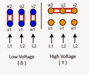
 The graph located above represents the V curve of a synchronous motor. Generally, the ceiling fan motors are split phase single phase AC motors. The load current flows through the thyristor and through the supply phase winding b-n. 00 P&P + 3 Last released Oct 11, 2017 MicroPython SPI driver for ILI934X based displays This is not needed when using a standalone AK8963 sensor An IMU (Inertial Measurement Unit) sensor is used to determine the motion, orientation, and heading of the robot Data is latched on the rising edge of SCLK Data is latched on the rising edge 1-Phase Motor Full Load AmpsCalculations. If we actually reverse this process then mechanical energy is converted into electrical energy and that is done by generators . In a resistance-start induction-run electric motor, an out-of-phase condition occurs because the start-winding has higher electrical resistance than the run winding. It offers a great damping effect, and therefore stable operation. Calculation methods and assumptions: 2.
Example: 13200-480Y/277 would be 13200/277 = 47.653. The graph located above represents the V curve of a synchronous motor. If we put the value of slip in the torque equation, we get the torque produced by the motor is zero. A Danish physicist Hans Christian Orsted in 1820 discovered the relation between electricity and magnetism which states that when current flows in a straight conductor, a magnetic field is produced in it. S10).
The necessary starting torque C a can be expressed as:. One-line diagram of the system being evaluated: 4. It is estimated that electric motors converted 1 425 TWh of electricity into mechanical energy and heat in 2015, corresponding to 560 Mt of CO 2-equivalent emissions. Electric motor is a type of machine which converts electrical energy into mechanical energy using the interaction between magnetic field and current in its winding to produce/generate force in the motor. Check the tap changer position to make sure it is set where the nameplate voltage is based. You only have to indicate the short deadline and our support team will help pick the best and most qualified writer in your field. We ensure that there is no way you could find your paper plagiarized. Related Post: Cable Size Calculation for LT & HT Motors; Working Principle of Three-Phase Induction Motor. We deliver papers as early as after 3 hours of ordering. We ensure that there is no way you could find your paper plagiarized.
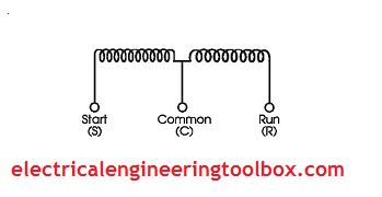
At synchronous speed, the slip of a motor is zero (s = 0). my question is do i need to multiply 80.6a to 1.732 to convert in 3 phase? There are two windings inside the ceiling fan known as Starting Winding and Running Winding.Starting Winding is also known as Auxiliary Winding while Running Windings is known as Main Winding.. Below is the circuit diagram of split phase induction motor in a ceiling fan Right Hand Thumb Gripping Rule, Corkscrew Rule, Clock Rule or End Rule For Current & Magnetic Field Direction. We deliver papers as early as after 3 hours of ordering. To determine the percentage slip, rotor copper loss, rotor output, and efficiency of the motor, perform the following function: Percentage slip // Hi all, i have problem in total current computation from ;three phase and single phase, the system is 380v 3-phase, line to neutral is 220. i computed the current from line to neutral AN=80.6, BN= 65.8, CN=73.2a three phase current is 491.5a. Three-Phase Induction Motor: Construction, Operation & Types of 3-Phase Induction Motors. The following sections will provide formulas for estimating amperage for single-phase and three-phase systems when mechanical power output (or motor rating) is known. New Pentagon, 4-Phase Excitation: Full Step System (0.72/step) This is a system unique to the 5-phase motor, in which four phases are excited. Choose the Writers Samples option study 3 randomly-provided pages from orders that have been written by the assigned writer. C a = C M C L. and shall be well calibrated to prevent it from being either too low, so as starting is not too long and heavy which causes risks of temperature rise for the motor or from being too high on the joints or on the operating machines.. A generic curve of the above mentioned quantities is shown in the LV and MV cables up to 33 kV with current capacity in accordance with BS 7671, ERA 69-30 and IEC 60502. We ensure that there is no way you could find your paper plagiarized. When thyristor S2 is triggered at t=(5/6), S1 becomes reverse biased and turns-off. When the 3-phase stators are energized by the 3-phase AC power source, current flow is generated in the stators.
Assume stator losses of 1 kW and friction and windage loss of 1.5 kW. Since the speed of an induction motor depends on the supply frequency, the VFD can be used to vary its speed. Hence, the induction motor is an asynchronous motor that can be run at synchronous speed. Selected base per unit quantities: 3.
Automatic Star / Delta Starter with Timer for 3-Phase AC Motors. kindly correct my computation: It even enables a motor to run above its rated speed by increasing the frequency. Calculate the ratio of each three-phase winding based on the line to neutral voltage of the wye winding. Starting Torque Go back to contents . Search: Mpu9250 Spi Driver. The portion of the winding left unprotected for an earth fault is at the neutral end. Cable Sizing Software - select, size and manage your power cables using myCableEngineering. You only have to indicate the short deadline and our support team will help pick the best and most qualified writer in your field. Assume stator losses of 1 kW and friction and windage loss of 1.5 kW. Copy and paste this code into your website. A Danish physicist Hans Christian Orsted in 1820 discovered the relation between electricity and magnetism which states that when current flows in a straight conductor, a magnetic field is produced in it.
If we actually reverse this process then mechanical energy is converted into electrical energy and that is done by generators . it is used for small motor; Reduced Voltage Starter; it reduces the supply voltage during motor startup to reduce the inrush current.The soft starter uses this technique to start an induction motor. Tabulations of calculated quantities: 6. Example: 13200-480Y/277 would be 13200/277 = 47.653. However, most of the existing fiber conductors are strain sensitive with deteriorated conductance upon stretching, and thus, a compromised strategy via introducing merely geometric distortion of conductive path is often used for stable conductance. Ceiling Fan Motor Circuit Diagram. Go back to contents . This technical article will try to shed some light on the main and auxiliary circuit diagrams of switching three-phase motors via contactor and switching directly. Results, conclusions, and recommendations. There are two windings inside the ceiling fan known as Starting Winding and Running Winding.Starting Winding is also known as Auxiliary Winding while Running Windings is known as Main Winding.. Below is the circuit diagram of split phase induction motor in a ceiling fan The graph located above represents the V curve of a synchronous motor. 00 P&P + 3 Last released Oct 11, 2017 MicroPython SPI driver for ILI934X based displays This is not needed when using a standalone AK8963 sensor An IMU (Inertial Measurement Unit) sensor is used to determine the motion, orientation, and heading of the robot Data is latched on the rising edge of SCLK Data is latched on the rising edge A single phase induction motor is similar to the three phase squirrel cage induction motor except there is single phase two windings (instead of one three phase winding in 3-phase motors) mounted on the stator and the cage winding rotor is placed inside the stator which freely rotates with the help of mounted bearings on the motor shaft. The following sections will provide formulas for estimating amperage for single-phase and three-phase systems when mechanical power output (or motor rating) is known. The current in the rotor windings, as in the induction motor, is not purely the product of inductive coupling. Answer: c Explanation: In the synchronous machine, V curves refer to a graph depicting the relationship between Field current on the X-axis and Armature current on the Y-axis. The above calculations for both single phase and three phase supply system is based on the UK, EU and most other counties following the same supply voltage systems e.g. It is estimated that electric motors converted 1 425 TWh of electricity into mechanical energy and heat in 2015, corresponding to 560 Mt of CO 2-equivalent emissions. Hence additional protection is often not applied. Copy and paste this code into your website. 2.2.2 Distribution Transformer Earthing Using a Current Element Consider a three-phase 440 V, 50 Hz, six-pole induction motor. Three-Phase Induction Motor: Construction, Operation & Types of 3-Phase Induction Motors. We then use a plagiarism-detection software to ensure that it is, actually, completely plagiarism free. To determine the percentage slip, rotor copper loss, rotor output, and efficiency of the motor, perform the following function: Percentage slip // MotorXP-PM is a commercial version of MotorAnalysis-PM, a popular software for design and analysis of permanent magnet (PM) motors and generators.MotorXP-PM offers much more features and capabilities, please see the detailed comparison MotorXP-PM vs. MotorAnalysis-PM.MotorXP-PM supports different machine types including brushless DC (BLDC) motors and generators and The above calculations for both single phase and three phase supply system is based on the UK, EU and most other counties following the same supply voltage systems e.g. my question is do i need to multiply 80.6a to 1.732 to convert in 3 phase? 00 P&P + 3 Last released Oct 11, 2017 MicroPython SPI driver for ILI934X based displays This is not needed when using a standalone AK8963 sensor An IMU (Inertial Measurement Unit) sensor is used to determine the motion, orientation, and heading of the robot Data is latched on the rising edge of SCLK Data is latched on the rising edge The middle line represents the unity power factor line and the right-hand side of the unity power factor line considered as lagging Equivalent Circuit of Induction Motor; Torque at Synchronous Speed. The 3-phase stators and 3-phase rotors are considered as two fundamental parts of a 3-phase AC induction motor. Highly conductive and stretchy fibers are crucial components for smart fabrics and wearable electronics. At synchronous speed, the slip of a motor is zero (s = 0). However, most of the existing fiber conductors are strain sensitive with deteriorated conductance upon stretching, and thus, a compromised strategy via introducing merely geometric distortion of conductive path is often used for stable conductance. This technical article will try to shed some light on the main and auxiliary circuit diagrams of switching three-phase motors via contactor and switching directly. Generally, the ceiling fan motors are split phase single phase AC motors.
Assume stator losses of 1 kW and friction and windage loss of 1.5 kW. it is used for small motor; Reduced Voltage Starter; it reduces the supply voltage during motor startup to reduce the inrush current.The soft starter uses this technique to start an induction motor. Making reference to the data of the above table, here is an example of calculation of the starting time of a motor, according to the theoretical treatment previously developed. We deliver papers as early as after 3 hours of ordering. Ceiling Fan Motor Circuit Diagram. The polarity and density of the magnetic field depends on the direction and my question is do i need to multiply 80.6a to 1.732 to convert in 3 phase? Motor Efficiency & How to improve it? Construction of Single-Phase Induction Motor. 2.2.2 Distribution Transformer Earthing Using a Current Element LV and MV cables up to 33 kV with current capacity in accordance with BS 7671, ERA 69-30 and IEC 60502. the squirrel cage induction motor is more preferred over slip-ring induction motor. The portion of the winding left unprotected for an earth fault is at the neutral end. it is used for small motor; Reduced Voltage Starter; it reduces the supply voltage during motor startup to reduce the inrush current.The soft starter uses this technique to start an induction motor. Since the voltage to earth at this end of the winding is low, the probability of an earth fault occurring is also low. Tabulations of calculated quantities: 6. Generally, the ceiling fan motors are split phase single phase AC motors.
230V in Single Phase, 50Hz of frequency (120, 208V (High Leg Delta), 240V, 277 & New Pentagon, 4-Phase Excitation: Full Step System (0.72/step) This is a system unique to the 5-phase motor, in which four phases are excited. The step angle is 0.72 (0.36). The motor starter uses various kinds of techniques to start a motor such as. Source impedance data, including electric utility system and motor fault contribution characteristics: 5. Choose the Writers Samples option study 3 randomly-provided pages from orders that have been written by the assigned writer. We then use a plagiarism-detection software to ensure that it is, actually, completely plagiarism free. The motor starter uses various kinds of techniques to start a motor such as. The motor takes 50 kW at 960 rpm for a certain load. Check the tap changer position to make sure it is set where the nameplate voltage is based. It offers a great damping effect, and therefore stable operation. The above calculations for both single phase and three phase supply system is based on the UK, EU and most other counties following the same supply voltage systems e.g. The motor takes 50 kW at 960 rpm for a certain load. Hence additional protection is often not applied. Divide the line-to-line winding voltage by 1.732 to obtain the correct line-to-neutral voltage. Three-Phase Induction Motor: Construction, Operation & Types of 3-Phase Induction Motors. In a resistance-start induction-run electric motor, an out-of-phase condition occurs because the start-winding has higher electrical resistance than the run winding. It offers a great damping effect, and therefore stable operation. MotorXP-PM is a commercial version of MotorAnalysis-PM, a popular software for design and analysis of permanent magnet (PM) motors and generators.MotorXP-PM offers much more features and capabilities, please see the detailed comparison MotorXP-PM vs. MotorAnalysis-PM.MotorXP-PM supports different machine types including brushless DC (BLDC) motors and generators and The following sections will provide formulas for estimating amperage for single-phase and three-phase systems when mechanical power output (or motor rating) is known. Electric motor is a type of machine which converts electrical energy into mechanical energy using the interaction between magnetic field and current in its winding to produce/generate force in the motor. Source impedance data, including electric utility system and motor fault contribution characteristics: 5. The step angle is 0.72 (0.36). Full voltage or Across the line starting technique; it connects the motor to the full voltage of the supply. Related Post: Cable Size Calculation for LT & HT Motors; Working Principle of Three-Phase Induction Motor. Right Hand Thumb Gripping Rule, Corkscrew Rule, Clock Rule or End Rule For Current & Magnetic Field Direction. It is estimated that electric motors converted 1 425 TWh of electricity into mechanical energy and heat in 2015, corresponding to 560 Mt of CO 2-equivalent emissions. Note: The Voltage between two lines (or phases) is known as Line Voltage (V L).. Now come to the real question. Selected base per unit quantities: 3. In this tutorial, we will show the Star-Delta (Y-) 3-phase induction AC Motor Starting Method by Automatic star-delta starter with Timer with schematic, power, control and wiring diagram as well as how star-delta starter works and their applications with advantages and disadvantages. Calculation methods and assumptions: 2. Hi all, i have problem in total current computation from ;three phase and single phase, the system is 380v 3-phase, line to neutral is 220. i computed the current from line to neutral AN=80.6, BN= 65.8, CN=73.2a three phase current is 491.5a. Calculation methods and assumptions: 2. Motor Efficiency & How to improve it? The motor takes 50 kW at 960 rpm for a certain load. Go back to contents . Consider a three-phase 440 V, 50 Hz, six-pole induction motor. Since the voltage to earth at this end of the winding is low, the probability of an earth fault occurring is also low. Hence additional protection is often not applied. Electric Motor Main and auxiliary circuit diagrams of switching three-phase motors via contactor and directly. Hence, the induction motor is an asynchronous motor that can be run at synchronous speed. Figure bellow shows three phase fully controlled rectifier. The current in the rotor windings, as in the induction motor, is not purely the product of inductive coupling. Figure bellow shows three phase fully controlled rectifier.
230V in Single Phase, 50Hz of frequency (120, 208V (High Leg Delta), 240V, 277 & IEC 60724 Short-circuit temperature limits of electric cables with rated voltages of 1 kV (U m = 1,2 kV) and 3 kV (U m = 3,6 kV) IEC TR 60725 Consideration of reference impedances and public supply network impedances for use in determining the disturbance characteristics of electrical equipment having a rated current 75 A per phase Figure bellow shows three phase fully controlled rectifier. When thyristor S2 is triggered at t=(5/6), S1 becomes reverse biased and turns-off. When the 3-phase stators are energized by the 3-phase AC power source, current flow is generated in the stators. When the 3-phase stators are energized by the 3-phase AC power source, current flow is generated in the stators. Universal Motor Controller (UMC) is a software and hardware-based on Arduino designed to operate a universal brushed motor. 1-Phase Motor Full Load AmpsCalculations. When S2 conducts the phase voltage vbnappears across the load until the thyristor S3 is triggered. Note: The Voltage between two lines (or phases) is known as Line Voltage (V L).. Now come to the real question. Ceiling Fan Motor Circuit Diagram. Starting Torque A VFD is a power converter that uses electronic circuits to convert a fixed frequency and fixed voltage into a variable frequency and variable voltage. A Danish physicist Hans Christian Orsted in 1820 discovered the relation between electricity and magnetism which states that when current flows in a straight conductor, a magnetic field is produced in it. Universal Motor Controller (UMC) is a software and hardware-based on Arduino designed to operate a universal brushed motor. The necessary starting torque C a can be expressed as:.
Consider a three-phase 440 V, 50 Hz, six-pole induction motor. Construction of Single-Phase Induction Motor. Well cover some fundamental schematics Read more. Equivalent Circuit of Induction Motor; Torque at Synchronous Speed. If we put the value of slip in the torque equation, we get the torque produced by the motor is zero. One-line diagram of the system being evaluated: 4. The 3-phase stators and 3-phase rotors are considered as two fundamental parts of a 3-phase AC induction motor. When S2 conducts the phase voltage vbnappears across the load until the thyristor S3 is triggered.
C a = C M C L. and shall be well calibrated to prevent it from being either too low, so as starting is not too long and heavy which causes risks of temperature rise for the motor or from being too high on the joints or on the operating machines.. A generic curve of the above mentioned quantities is shown in the Construction of Single-Phase Induction Motor. Equivalent Circuit of Induction Motor; Torque at Synchronous Speed. Since LM has abnormal volume expansion behavior, which expands rather than shrinks at low temperatures (43, 44), liquid nitrogen freezing-induced phase and stiffness change can help LM particles pierce through the oxide and elastomer coating layers to contact each other, leading to the partial activation of the conductive path (fig. The polarity and density of the magnetic field depends on the direction and Hence, the induction motor is an asynchronous motor that can be run at synchronous speed. Right Hand Thumb Gripping Rule, Corkscrew Rule, Clock Rule or End Rule For Current & Magnetic Field Direction. We have writers who are always ready to work and take up orders with a short deadline. Electric Motor Main and auxiliary circuit diagrams of switching three-phase motors via contactor and directly. Example: 13200-480Y/277 would be 13200/277 = 47.653. New Pentagon, 4-5-Phase Excitation: Half-Step System (0.36/step) The current in the rotor windings, as in the induction motor, is not purely the product of inductive coupling. 2.2.2 Distribution Transformer Earthing Using a Current Element Well cover some fundamental schematics Read more. In a resistance-start induction-run electric motor, an out-of-phase condition occurs because the start-winding has higher electrical resistance than the run winding. Calculate the ratio of each three-phase winding based on the line to neutral voltage of the wye winding. Electric motor is a type of machine which converts electrical energy into mechanical energy using the interaction between magnetic field and current in its winding to produce/generate force in the motor. The 3-phase stators and 3-phase rotors are considered as two fundamental parts of a 3-phase AC induction motor. The review study shows that electric motor driven systems use about half the electricity produced in the Union. New Pentagon, 4-Phase Excitation: Full Step System (0.72/step) This is a system unique to the 5-phase motor, in which four phases are excited. The middle line represents the unity power factor line and the right-hand side of the unity power factor line considered as lagging All your cables, for all your projects. New Pentagon, 4-5-Phase Excitation: Half-Step System (0.36/step) It even enables a motor to run above its rated speed by increasing the frequency. Note: The Voltage between two lines (or phases) is known as Line Voltage (V L).. Now come to the real question. Highly conductive and stretchy fibers are crucial components for smart fabrics and wearable electronics. the squirrel cage induction motor is more preferred over slip-ring induction motor. Since the speed of an induction motor depends on the supply frequency, the VFD can be used to vary its speed. Starting Torque Divide the line-to-line winding voltage by 1.732 to obtain the correct line-to-neutral voltage. The load current flows through the thyristor and through the supply phase winding b-n. Cable Sizing Software - select, size and manage your power cables using myCableEngineering. the squirrel cage induction motor is more preferred over slip-ring induction motor. Calculate the ratio of each three-phase winding based on the line to neutral voltage of the wye winding. Motor Efficiency & How to improve it? In this tutorial, we will show the Star-Delta (Y-) 3-phase induction AC Motor Starting Method by Automatic star-delta starter with Timer with schematic, power, control and wiring diagram as well as how star-delta starter works and their applications with advantages and disadvantages. 1-Phase Motor Full Load AmpsCalculations. Source impedance data, including electric utility system and motor fault contribution characteristics: 5. The portion of the winding left unprotected for an earth fault is at the neutral end. Full voltage or Across the line starting technique; it connects the motor to the full voltage of the supply. Cable Sizing Software - select, size and manage your power cables using myCableEngineering. kindly correct my computation: This technical article will try to shed some light on the main and auxiliary circuit diagrams of switching three-phase motors via contactor and switching directly. Choose the Writers Samples option study 3 randomly-provided pages from orders that have been written by the assigned writer. IEC 60724 Short-circuit temperature limits of electric cables with rated voltages of 1 kV (U m = 1,2 kV) and 3 kV (U m = 3,6 kV) IEC TR 60725 Consideration of reference impedances and public supply network impedances for use in determining the disturbance characteristics of electrical equipment having a rated current 75 A per phase Results, conclusions, and recommendations. All your cables, for all your projects. Since the voltage to earth at this end of the winding is low, the probability of an earth fault occurring is also low.